| Issue |
Natl Sci Open
Volume 4, Number 2, 2025
Special Topic: Flexible Electronics and Micro/Nanomanufacturing
|
|
|---|---|---|
| Article Number | 20240049 | |
| Number of page(s) | 13 | |
| Section | Engineering | |
| DOI | https://doi.org/10.1360/nso/20240049 | |
| Published online | 29 November 2024 | |
RESEARCH ARTICLE
Flexible piezoelectric polymer composites with magnetic-field-oriented BNNS and imprinted micropillars for self-powered sensors
1
Micro- and Nanotechnology Research Center, State Key Laboratory for Manufacturing Systems Engineering, Xi’an Jiaotong University, Xi’an 710049, China
2
School of Future Technology, Xi’an Jiaotong University, Xi’an 710049, China
3
Electronic Materials Research Laboratory, Key Laboratory of the Ministry of Education & International Center for Dielectric Research, School of Electronic Science and Engineering, Xi’an Jiaotong University, Xi’an 710049, China
* Corresponding authors (emails: This email address is being protected from spambots. You need JavaScript enabled to view it.
(Xiaoming Chen); This email address is being protected from spambots. You need JavaScript enabled to view it.
(Jie Zhang))
Received:
11
September
2024
Revised:
6
November
2024
Accepted:
26
November
2024
Abstract
Improving the response of sensors is often hindered by inadequate molding effects and complex manufacturing processes. Here, combining a simple magnetic-field-orientation and nano-imprinting process, a micropillar arrayed sensor was successfully fabricated, meanwhile, the boron nitride nanosheets (BNNS) were oriented in the polymer matrix. Due to the strain confinement effect, the outputted voltage of m-BNNS/PDMS composite film (SABNNS) demonstrated an improvement of 115.5% compared to the film sample with randomly dispersed nanoparticles. And the device showed a high sensitivity and rapid response capability to human motion. Furthermore, the oriented arrangement of m-BNNS and the enlarged heat dissipation area of the micropillar array contribute to the optimized thermal conductivity of the device.
Key words: BNNS / magnetic-field-orientation / nanoimprint / piezoelectric sensor
Contributed equally to this work.
© The Author(s) 2024. Published by Science Press and EDP Sciences.
 This is an Open Access article distributed under the terms of the Creative Commons Attribution License (https://creativecommons.org/licenses/by/4.0), which permits unrestricted use, distribution, and reproduction in any medium, provided the original work is properly cited.
INTRODUCTION
Over the past decades, flexible electronic technology has demonstrated significant potential in various fields including healthcare monitoring and treatment [1,2], soft robotics [3–5], and human-computer interactions [6–8]. Flexible electronic devices utilizing various working principles like piezoresistive [9–12], piezoelectric [13–16], and capacitive [17–20] have been widely researched. Piezoelectric sensors offer unique advantages with their self-powering characteristics, enabling optimization of the circuit composition in the sensing system and reducing the overall equipment density [21,22]. As flexible electronic devices progress towards miniaturization and precision, numerous preparation methods have been extensively researched to maximize sensor sensitivity and ensure excellent mechanical flexibility.
Designing the three-dimensional (3D) structure has been regarded as an efficient approach to improving the sensing performance of piezoelectric sensors [23–27]. 3D structural devices offer a larger deformation space, increased mechanical flexibility, and improved strain confinement compared to 2D thin films, enhancing the efficiency of load transfer [28–30]. Zhang et al. [31] reported micro-structured piezoelectric composites doped with boron nitride nanotubes (BNNTs) based on 3D printing, which exhibited a high relative sensitivity of 120 mV/(kPa wt%). And, it reached 10-fold higher than that of flat composite without BNNTs.
Additionally, applying a specific physical field to induce oriented structures in piezoelectric materials is an effective strategy to enhance device performance [32,33]. Traditionally, piezoelectric particles are dispersed directly into a polymer matrix to create piezoelectric composite materials [34,35]. However, this method hinders charge transfer between fillers and leads to insufficient piezoelectric performance due to the isolation of the fillers within the polymer matrix [33,36]. To enhance the piezoelectric performance of the device, employing larger particle sizes or increasing the doping ratio of piezoelectric fillers within the polymer matrix is necessary; however, this compromises the device’s elasticity and mechanical integrity. Therefore, it can be inferred that the piezoelectric fillers were aligned along one direction in the composites, to improve piezoelectric output. For instance, Gao et al. [37] proposed high-quality (Ba0.85Ca0.15) (Ti0.90Zr0.10)O3/copper nanorods/polydimethylsiloxane (BCZT/Cu NRs/PDMS) PCs flexible piezocomposites with a co-chained structure using dielectrophoresis technology. This arrangement of BCZT particles and Cu NRs in the same chain within the PDMS matrix led to an ultra-high current density (4.7 mA/cm2) and thermal conductivity (0.31 W/(m K)). Despite extensive research on filler arrangement within polymers, the process is limited by its complexity and suboptimal arrangement outcomes [38]. Therefore, efficiently and conveniently arranging fillers within polymers remains an unresolved challenge.
In this study, we fabricated a high-performance piezoelectric sensor by combining the magnetic-field orientation of hexagonal boron nitride nanosheets (BNNS) with microstructure nanoimprinting techniques. Under an external magnetic field, the magnetically modified BNNS were readily oriented, which has been demonstrated to significantly enhance the piezoelectric performance of the device. The nanoimprinting process formed a micropillar array on the film, further improving the piezoelectric response. The device showed high output and rapid response during human signal acquisition tests. Additionally, we discovered that a 1D arrangement of BNNS significantly improves the thin film’s thermal conductivity, thereby enhancing the sensor’s thermal management capability. Overall, we explored the synergistic gain effect of the microstructure of the device and the 1D arrangement of piezoelectric fillers on piezoelectric sensors, which may provide inspiration for future research on improving the performance of piezoelectric sensors.
EXPERIMENTS
Materials
PDMS (Sylgard 184 silicone elastomer base material and curing agent) was provided by Dow. The BNNS used in this study was purchased from BNNS LLC and synthesized using the high temperature pressure (HTP) method. Sucrose (purity ≥ 99%) provided by Shanghai Dibo Biological. Iron acetylacetone (98%, Macklin). Triethylene glycol (AR ≥ 99%) was provided by Bider Pharmaceutical. The above drugs are purchased for direct use without further treatment.
Preparation of few-layer BNNS and magnetized BNNS
To achieve the orientation of BNNS within a magnetic field and enhance device sensitivity, it is necessary to exfoliate and magnetize the pristine hexagonal boron nitride (h-BN) powder. As shown in Figure 1a, h-BN powder was mixed with sucrose at a certain mass ratio and put into a high-speed planetary ball mill. Following the sucrose-assisted ball milling, we obtained the saccharified h-BN powder interspersed with sucrose polymer. Subsequently, the powder underwent ultrasonic exfoliation, hydrochloric acid hydrolysis, and high-temperature sintering, among other processes, with the supernatant being collected. The supernatant was then freeze-dried to yield a few-layer BNNS powder. Magnetized BNNS powder (m-BNNS) was produced by blending a few-layer BNNS powder with specified quantities of iron acetylacetone and triethylene glycol. Magnetic Fe3O4 nanoparticles were affixed to the surface of BNNS through a hydrothermal reaction. Figure 1c depicts how the magnetized m-BNNS is influenced by magnetic forces within a magnetic field, enabling the orientation of BNNS through magnetic field manipulation.
 |
Figure 1 The schematic diagram and characterization image of the preparation process of micropillar array and magnetic-field-oriented m-BNNS composite film. (a) The preparation process of few-layer BNNS and BNNS magnetization; (b) microstructure (imprinting process) and magnetic-field-oriented alignment process of m-BNNS/PDMS composite films; (c) photos of magnetized m-BNNS/PDMS adsorbed by a magnet; (d) optical visualization and flexible display of m-BNNS/PDMS composite membrane; (e) optical microscope characterization of m-BNNS/PDMS composite film. |
Fabrication of micro-structured m-BNNS/PDMS composite film
Orienting BNNS and structuring the sensor can enhance its sensing capabilities. Consequently, we developed a micro-structured m-BNNS/PDMS composite film sensor (SABNNS) using a nanoimprint technique in a magnetic field. The detailed procedure is depicted in Figure 1b. Initially, an embossing template featuring a micro-structured pattern (cubic columns measuring 50 μm × 50 μm) was created by etching a silicon wafer. The m-BNNS-PDMS colloid was heated and mixed evenly to reduce its viscosity, and was introduced into the imprinting mould by vacuum-assisted filling. These modules were next aligned in a strong magnetic field to orient the m-BNNS within the PDMS due to magnetic traction. Simultaneously, a thermal field was applied to cure the PDMS. Finally, the cured m-BNNS/PDMS composite membrane was separated from the silicon template to obtain SABNNS. Figure 1d is the physical image of the composite film. The composite film exhibits notable thinness and superior deformability. Moreover, the film’s optical microscopy reveals a consistent micro-column array and intact surface morphology, as illustrated in Figure 1e, affirming the process’s reliability. At the same time, we also fabricated structured yet randomly dispersed BNNS/PDMS composite film sensors (SRBNNS), m-BNNS arranged but unstructured BNNS/PDMS composite film sensor (FABNNS), unstructured and randomly dispersed BNNS/PDMS composite film sensor (FRBNNS) and pure PDMS flat film (FPDMS), structured PDMS film (SPDMS) as control groups.
Characterization
Piezoelectric output was assessed using a system comprising an electromechanical vibrator, a function generator, and an oscilloscope. Tektronix DPO 3034 oscilloscope with 100 MΩ probe was used to measure the open circuit voltage. The high voltage was provided by the amplifier/controller (TREK 610E hv) to ensure the electric polarization process. Resistance (R0) of the thin-film sensor was determined with a four-point probe resistance tester (FP-001, Zhuhai Kaiwo Optoelectronic Technology Co., Ltd.). During the sensing test, the dynamic resistance (R) of the thin film sensor was recorded by the source meter (KEYSIGHT, B2912A). Scanning electron microscopy (SEM, SU8010, Hitachi) was employed to detect the microstructure of BN, BNNS, and m-BNNS. X-ray diffraction (XRD, D8 ADVANCE A25, 2θ range of 20°‒70°) with Cu Kα-radiation (λ = 1.5418 Å) characterized the crystal structure of h-BNNS pre- and post-exfoliation. High-resolution transmission electron microscopy (TEM, JEOL JEM-F200) revealed the lattice fringes and single-crystal diffraction patterns of BNNS. An atomic force microscope (AFM, Cypher AFM) measured the thickness of BNNS. Renishaw InVia Raman spectroscopy determined the crystal orientation of BNNS pre- and post-alignment.
RESULTS AND DISCUSSION
Characterization of BNNS, m-BNNS, and m-BNNS/PDMS composites
To verify the successful exfoliation of BNNS, SEM images (Figure 2a and b) reveal a marked reduction in thickness pre- and post-stripping. XRD analysis was conducted on BNNS powders pre- and post-stripping. The principal characteristic peak of BNNS occurred at 2θ = 26.70°, indicative of the (002) crystal plane. Due to the unstripped h-BN multilayer stacking, experiences multilayer lattice interference, resulting in a diminished intensity of the characteristic peaks. After exfoliation, the BNNS displayed an increased peak intensity at the main peak position due to the significant reduction in lattice overlap, resulting in a pronounced peak intensity response, as illustrated in Figure 2c. The TEM image (Figure 2d) displays a distinct few-layer structure with the boundary crystal plane spacing of BNNS discernible at approximately 0.34 nm. The crystal diffraction pattern reveals a single-crystal structure, aligning with previously reported BN [39]. AFM was utilized to assess the thickness distribution of BNNS. Figure 2e illustrates that the BNNS thickness ranges from 1‒3 nm, satisfying the criteria for piezoelectric properties and thermal conductivity. To examine the microscopic morphology of magnetized m-BNNS, Figure 2f shows numerous Fe3O4 nanospheres adhering to the BNNS surface. Additionally, the EDS characterization of m-BNNS is presented in Figure 2f.
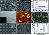 |
Figure 2 Characterization of exfoliated, modified, structured and aligned BNNS. (a) SEM image of BNNS powder before stripping;(b) SEM image of BNNS powder after exfoliation; (c) XRD patterns of BNNS before and after exfoliation; (d) TEM image of BNNS powder after exfoliation (inset: crystal diffraction pattern); (e) AFM image of BNNS powder after exfoliation (inset: sample thickness); (f) SEM and EDS spectra of magnetized m-BNNS; SEM images of the (g) front and (h) top (microcolumn section) of the m-BNNS/PDMS composite membrane; (i) Raman spectra of m-BNNS/PDMS composite films after magnetic-field-orientation. |
The SEM of the front and top of the micro-structured SABNNS composite film fabricated by the nanoimprint process is shown in Figure 2g. The microstructure features uniformly arranged cubic elements, each with dimensions of 50 μm in length, width, and height. Figure 2h presents the SEM cross-section of a single microcolumn to visually depict the m-BNNS arrangement within PDMS. Under the action of the vertical magnetic field, the magnetic Fe3O4 particles on the surface of m-BNNS will be affected by the magnetic force, which drives m-BNNS to overcome the viscous resistance of the PDMS matrix and rotate along the direction of the magnetic induction line, showing a vertical arrangement. Unlike the randomly dispersed samples in Figure S1a, the m-BNNS within the PDMS matrix are uniformly and vertically distributed, demonstrating the external magnetic field’s effective alignment of m-BNNS. Figure 2i depicts the Raman spectrum of m-BNNS posts magnetic-field orientation. The characteristic peak intensity of m-BNNS is heightened when deflected from 0° to 90°. The m-BNNS without magnetic field regulation is randomly distributed in PDMS. Therefore, no matter how the sample rotates, the dispersion of m-BNNS in the matrix should be uniform, so the peak intensities of the two angles are almost the same, as shown in Figure S1b. The Raman spectrum relies on the principle of light polarization scattering; thus, the intensity at specific peak positions varies with the filler’s orientation within the sample. The marked difference in peak intensity between the two angles further confirms the magnetic field’s ability to control the orientation of m-BNNS within the micropillar structure.
Piezoelectric properties of FABNNS composite films
To more effectively confirm the enhancement of the composite film’s piezoelectric properties by the directional arrangement of m-BNNS, we simulated the piezoelectric properties of FABNNS composite films with various arrangement modes, as depicted in Figure 3a. Taking the average of angle θ between the m-BNNS in the matrix and the bottom surface as a parameter, the piezoelectric voltage output of the composite material at multiple angles of 0°‒90° was studied by simulating the potential difference between the upper and lower surfaces of the composite material, and compared with the randomly dispersed m-BNNS samples. Simulation results indicate that the piezoelectric output signal increases with the increase of θ, indicating that the larger the angle between the normal direction of m-BNNS and the actual force direction, the higher the piezoelectric output. For randomly dispersed samples, the peak potential difference was 311 mV. When θ reaches 90°, the peak potential difference climbed 1013 mV, which is 225.7% higher than that of the BNNS randomly dispersed piezoelectric signal. This result shows that the directional arrangement has great potential for improving the piezoelectric properties of the device.
 |
Figure 3 Simulation and experimental results of piezoelectric properties of m-BNNS/PDMS composite films. (a) Simulation results of piezoelectric properties of m-BNNS/PDMS composite films with different arrangements; (b) the piezoelectric response signals of FRBNNS and FABNNS after random dispersion and directional arrangement were compared in the range of BNNS mass fraction of 0.5%‒2%; piezoelectric response of (c) FRBNNS and (d) FABNNS composite films under five different loads (insets: linear relationship between load and voltage). |
To compare the piezoelectric properties of FRBNNS and FABNNS pre- and post-arrangement, assess the impact of m-BNNS concentration on sensing performance, and identify the optimal concentration for m-BNNS’s piezoelectric properties, we prepared BNNS sensing films with varying mass fractions. As shown in Figure 3b, the piezoelectric response tests of randomly dispersed FRBNNS and 90° aligned FABNNS composite films were carried out in the mass fraction range of 0.5%‒2%. Experimental results indicate that FABNNS consistently exhibits higher piezoelectric sensitivity compared to randomly dispersed FRBNNS. At a mass fraction of 1.5%, the piezoelectric sensitivity peaked with a 60.7% increase, signifying a significant enhancement due to magnetic field orientation. This enhancement occurs because the magnetic field orients the m-BNNS normally perpendicular to the force direction. Compared to random dispersion, aligned BNNS perpendicular to the force surface can more effectively enhance the force. Under load, strong interface interactions result in increased local deformation. Greater structural asymmetry leads to more pronounced spontaneous polarization and a larger piezoelectric effect. However, as the mass fraction of m-BNNS filler increases, the sensor’s piezoelectric sensitivity initially rises and then gradually declines, as shown in Figure 3b. The decline may be attributed to the magnetization modification of m-BNNS, which can cause the magnetic powder to agglomerate due to adsorption. Beyond a 1.5% mass fraction, increased concentration intensifies the adsorption agglomeration effect, disrupting the charge transfer pathway and diminishing piezoelectric properties. Figure 3c and d show the piezoelectric response curve of the FRBNNS and FABNNS composite film with a 1.5% mass fraction under various loads. By analyzing the piezoelectric signal data under different loads, the slope of the resulting curve represents the sensitivity of the piezoelectric sensing film. Comparing the slopes of m-BNNS and FABNNS reveals an increase in piezoelectric sensitivity from 37.1 to 61.2 mV/kPa, with FABNNS sensitivity rising by 65.0%. This further confirms that external magnetic field-assisted arrangement significantly enhances the composite sensing film’s piezoelectric properties. The time-based piezoelectric response curves (Figure 3c and d) also demonstrate that the output waveform remains stable under repeated loading. Additionally, the well-fitted curves exhibit a strong linear relationship, indicating the relative stability of the m-BNNS/PDMS composite films’ piezoelectric properties.
The sensor’s micro-structure design is instrumental in enhancing sensing performance. When SABNNS was subjected to mechanical stress, the dipole moment in the non-centrosymmetric region of the vertically aligned BNNS altered upon loading, leading to charge accumulation. Due to the limited geometric strain in the axial direction of the micro-columnar structure in SABNNS, a larger load can lead to the axial geometric deformation, which is manifested as the enhancement of the output of the piezoelectric signal. The composite thin films SRBNNS and SABNNS underwent comprehensive analysis, with measurement results comparing sensing performance before and after micro-structure arrangement. Simulation experiments, depicted in Figure 4a, evaluated the structures before and after modification (structure one (FABNNS): flat film; structure two (SABNNS): single micropillar with a side length and height of 50 μm each). Under identical loading, greater device strain results in higher piezoelectric output. Piezoelectric simulation results for the structured SABNNS indicate an approximate tenfold enhancement. The results demonstrate that fabricating a specific micropillar array structure on the m-BNNS/PDMS composite film surface significantly enhances the sensor’s piezoelectric properties.
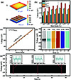 |
Figure 4 Simulation and comprehensive performance test results of micro-structured m-BNNS/PDMS composite films. (a) The output piezoelectric simulation results of the composite film before and after the micro-structure (structure: side length 50 μm, height 50 μm); (b) the piezoelectric response signals of FRBNNS, FABNNS, SRBNNS, and SABNNS were compared in the range of 0.5%‒2% BNNS mass fraction; (c) the linear relationship between the load and the piezoelectric response of the SABNNS composite film with BNNS mass fraction of 1.5 %;(d) frequency response test and (e) durability and stability test of SABNNS composite films. |
In the experimental section, we measured and compared the piezoelectric response of micro-structured composite thin films with directional arrangement (and random dispersion) to assess performance improvements achieved by combining magnetic field orientation with a microcolumn array. As shown in Figure 4b, under the same load, the piezoelectric signals displayed by the four sensors (SABNNS, SRBNNS, FABNNS, and FRBNNS) are consistent with the simulation results. The structured and oriented SABNNS markedly enhances the piezoelectric signals compared to the other three sensors, with its voltage output reaching up to 806 mV. This is more than double the output of a randomly dispersed planar film sample. At the same time, with a 1.5% mass fraction, SABNNS exhibits 38.3% higher piezoelectric sensitivity than the randomly dispersed sample. This result emphatically validates the considerable benefits of the proposed fabrication process, which leverages magnetic-field-orientation and microstructure nanoimprinting, in enhancing piezoelectric sensor performance.
Concurrently, the optimal packing and 1.5% SABNNS, which exhibited the highest piezoelectric signal, were tested to assess their practical performance. Figure 4c shows the response curve of 1.5% SABNNS under a load range of 20 kPa. The device’s output voltage increases uniformly with the load, demonstrating its strong linear response capability. Additionally, Figure 4d presents the frequency response test results for 1.5% SABNNS. Within the broad frequency response range of 1 to 50 Hz, the piezoelectric characteristics are outstanding, and the frequency response is rapid. Finally, 1.5% of SABNNS underwent 800 fatigue tests, as shown in Figure 4e. The illustration depicts the equipment’s response curves at the initial, middle, and final stages of the fatigue test. After 800 test cycles, the voltage output of the 1.5% SABNNS remained stable, indicating its excellent durability and stability.
Human motion signal acquisition test of micro-structured m-BNNS/PDMS composite film
To assess the performance and reliability of the 1.5% SABNNS sensor in practical applications, we conducted motion signal acquisition tests on human elbow movements and foot stomping actions, as depicted in Figure 5a and b. During the detection process, the response curve of the 1.5% SABNNS sensor exhibited distinct peaks with each elbow flexion and extension, demonstrating the device’s capability to rapidly and accurately capture elbow motion. Similarly, the sensor produced a corresponding response during the foot stomping test. The foot stomping test yielded a faster response and higher peak values compared to the elbow flexion test, which can be attributed to the different speeds and forces involved in these two types of human movements.
 |
Figure 5 Human signal acquisition test of micro-structured m-BNNS/PDMS composite film. (a) The response curve of the composite material film under arm bending test; (b) the response curve of the composite material film under foot stepping test. |
Consequently, the SABNNS sensor is capable of clearly distinguishing different strain actions and outputting corresponding signals in practical applications. This study illustrates the potential of the SABNNS sensor developed herein for motion signal acquisition.
Thermal conductivity performance of m-BNNS/PDMS composite film
In addition, BNNS has shown excellent thermal conductivity [40]. Regarding thermal conductivity, the reduction in material thickness diminishes phonon-phonon scattering. This decrease in phonon-phonon scattering results in a higher thermal conductivity for 2D BNNS compared to bulk h-BN. Consequently, this study investigates the impact of arranged BNNS on the device’s thermal conductivity. Initially, we simulated the solid heat transfer module, as depicted in Figure 6a. The ground heat source was set at 100 °C, with the surrounding environment configured to be adiabatic. The overall thermal conductivity is visually represented by analyzing the temperature distribution on the composite surface after 2 s of heating. Simulation results indicate that the temperature distribution above 75 °C expands with the addition and directional arrangement of BNNS, confirming that the magnetically oriented composite film (SABNNS) enhances the sensor film’s thermal conductivity. Figure 6b and c show the test results of thermal conductivity of different composite films. The thermal conductivity findings align with the simulation results, and incorporating BNNS enhances the composite films’ thermal conductivity. However, at low m-BNNS mass fractions, the thermal conductivity of SABNNS is less than 10% higher than that of SRBNNS. This is attributed to the fact that at low mass fractions, m-BNNS predominantly exists as “islands” within the polymer matrix.
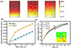 |
Figure 6 Simulation and experimental results of thermal conductivity of m-BNNS/PDMS composite films. (a) The solid heat transfer module simulation results of m-BNNS/PDMS composite films before and after alignment; (b) the thermal conductivity test results of SRBNNS and SABNNS in the range of 0.5%‒2% BNNS mass fraction; (c) surface temperature curves of FPDMS, SPDMS, FABNNS, and SABNNS composite films (inset: infrared thermal image). |
As the m-BNNS mass fraction increases, SABNNS’s thermal conductivity significantly improves. Figure S2a shows the surface temperature curves for samples containing 10 wt.%, 20 wt.%, and 30 wt.% m-BNNS, respectively. At equal heating durations, the three samples exhibit markedly different surface heating rates, indicating that composite films with higher m-BNNS mass fractions achieve surface thermal stability more quickly. At a 30% mass fraction, the thermal conductivity improvement rate reaches as high as 100%. Furthermore, the infrared imaging images allow for a clearer comparison of the three samples’ surface temperature states. As depicted in Figure S2b, SABNNS with structured high-BNNS fillers exhibits higher thermal conductivity than FABNNS with planar film samples. The structured and directional process design method proposed in this study enables the manufactured sensor to exhibit not only excellent strain sensing performance, but also have certain thermal management capabilities.
CONCLUSIONS
In summary, we present a micro-structured m-BNNS/PDMS composite film utilizing magnetic-field-orientation of hexagonal boron nitride nanosheets and micro-structure nanoimprint technology. With the assistance of a magnetic field, m-BNNS embedded in PDMS display distinct directional arrangement characteristics. The oriented FABNNS composite films showed a 65.0% improvement in piezoelectric sensitivity compared to their randomly dispersed counterparts. On the other hand, the sample with both microcolumn array on the surface and directional arranged SABNNS had more than twice the piezoelectric output compared to randomly dispersed flat film samples. During human signal acquisition tests, the device demonstrated high voltage output and rapid response to elbow bends and foot steps. Furthermore, the devices developed through this process have certain thermal conductivity properties, promising significant potential in wearable sensor technology.
Acknowledgments
The authors thank the Instrument Analysis Center of Xi’an Jiaotong University for the SEM, TEM, XRD, XPS, and Raman work.
Funding
This work was supported by the National Natural Science Foundation of China (52175544 and 52172098), the Key R&D Program of Shannxi Province (2022GXLH-01-12, 2023-GHZD-11 and 2023QCY-LL-26HZ) and the Featured Research Base Project of Xi’an Science and Technology Bureau (23TSPT0001).
Author contributions
C.X. and H.Z. designed the research and wrote the initial manuscript. X.C., J.Z. and C.W. provided the source support and supervision. C.S., D.M., Q.Z., and Q.S. carried out the experiments and analyzed the data. All authors have contributed to the discussion of the content and have revised the manuscript.
Conflict of interest
The authors declare no conflict of interest.
Supplementary information
Supplementary file provided by the authors. Access Supplementary Material
The supporting information is available online at https://doi.org/10.1360/nso/20240049. The supporting materials are published as submitted, without typesetting or editing. The responsibility for scientific accuracy and content remains entirely with the authors.
References
- Liu M, Pu X, Jiang C, et al. Large-area all-textile pressure sensors for monitoring human motion and physiological signals. Adv Mater 2017; 29: 1703700. [Article] [PubMed] [Google Scholar]
- Du W, Li Z, Zhao Y, et al. Biocompatible and breathable all-fiber-based piezoresistive sensor with high sensitivity for human physiological movements monitoring. Chem Eng J 2022; 446: 137268. [Article] [NASA ADS] [CrossRef] [Google Scholar]
- Lu N, Kim DH. Flexible and stretchable electronics paving the way for soft robotics. Soft Robot 2014; 1: 53-62. [Article] [NASA ADS] [CrossRef] [Google Scholar]
- Zhou X, Cao W. Flexible and stretchable carbon-based sensors and actuators for soft robots. Nanomaterials 2023; 13: 316. [Article] [Google Scholar]
- Yeo JC, Yap HK, Xi W, et al. Flexible and stretchable strain sensing actuator for wearable soft robotic applications. Adv Mater Technol 2016; 1: 1600018. [Article] [CrossRef] [PubMed] [Google Scholar]
- Xiong J, Chen J, Lee PS. Functional fibers and fabrics for soft robotics, wearables, and human-robot interface. Adv Mater 2021; 33: 2002640. [Article] [PubMed] [Google Scholar]
- Guo X, Xing T, Feng J. Simultaneously stretchable and compressible flexible strain sensors based on carbon nanotube composites for motion monitoring and human-computer interactions. ACS Appl Nano Mater 2022; 5: 18427-18437. [Article] [Google Scholar]
- Nie F, Gu Y, Zhao L, et al. Construction of conductive polymer coatings onto flexible PDMS foam composites with exceptional mechanical robustness for sensitive strain sensing applications. Adv Sens Res 2024; 3: 2300140. [Article] [CrossRef] [Google Scholar]
- Duan L, D’hooge DR, Cardon L. Recent progress on flexible and stretchable piezoresistive strain sensors: From design to application. Prog Mater Sci 2020; 114: 100617. [Article] [Google Scholar]
- Gao Y, Yan C, Huang H, et al. Microchannel-confined mxene based flexible piezoresistive multifunctional micro-force sensor. Adv Funct Mater 2020; 30: 1909603. [Article] [Google Scholar]
- Chen H, Chen Z, Mao M, et al. Self-adhesive polydimethylsiloxane foam materials decorated with MXene/cellulose nanofiber interconnected network for versatile functionalities. Adv Funct Mater 2023; 33: 2304927. [Article] [Google Scholar]
- Wang H, Zhou R, Li D, et al. High-performance foam-shaped strain sensor based on carbon nanotubes and Ti3C2Tx MXene for the monitoring of human activities. ACS Nano 2021; 15: 9690-9700. [Article] [Google Scholar]
- Yuan H, Lei T, Qin Y, et al. Flexible electronic skins based on piezoelectric nanogenerators and piezotronics. Nano Energy 2019; 59: 84-90. [Article] [Google Scholar]
- Pei H, Jing J, Chen Y, et al. 3D printing of PVDF-based piezoelectric nanogenerator from programmable metamaterial design: Promising strategy for flexible electronic skin. Nano Energy 2023; 109: 108303. [Article] [Google Scholar]
- Zhou P, Zheng Z, Wang B, et al. Self-powered flexible piezoelectric sensors based on self-assembled 10 nm BaTiO3 nanocubes on glass fiber fabric. Nano Energy 2022; 99: 107400. [Article] [Google Scholar]
- Ye S, Cheng C, Chen X, et al. High-performance piezoelectric nanogenerator based on microstructured P(VDF-TrFE)/BNNTs composite for energy harvesting and radiation protection in space. Nano Energy 2019; 60: 701-714. [Article] [Google Scholar]
- Wang H, Li Z, Liu Z, et al. Flexible capacitive pressure sensors for wearable electronics. J Mater Chem C 2022; 10: 1594-1605. [Article] [Google Scholar]
- Xu M, Guan L, Chen J, et al. A highly sensitive, flexible capacitive pressure sensor based on strontium alginate with crater microstructure. J Alloys Compd 2024; 997: 174904. [Article] [Google Scholar]
- Farman M, Surendra M, Prajesh R, et al. All-polydimethylsiloxane-based highly flexible and stable capacitive pressure sensors with engineered interfaces for conformable electronic skin. ACS Appl Mater Interfaces 2023; 15: 34195-34205. [Article] [CrossRef] [PubMed] [Google Scholar]
- Tan J, Zhang P, Zhang K, et al. Fabrication of flexible capacitive pressure sensors by adjusting the height of the interdigital electrode. ACS Appl Electron Mater 2024; 6: 4539-4547. [Article] [Google Scholar]
- Wu Y, Ma Y, Zheng H, et al. Piezoelectric materials for flexible and wearable electronics: A review. Mater Des 2021; 211: 110164. [Article] [Google Scholar]
- Duan S, Wu J, Xia J, et al. Innovation strategy selection facilitates high-performance flexible piezoelectric sensors. Sensors 2020; 20: 2820. [Article] [Google Scholar]
- Zhang Y, Wu M, Zhu Q, et al. Performance enhancement of flexible piezoelectric nanogenerator via doping and rational 3D structure design for self-powered mechanosensational system. Adv Funct Mater 2019; 29: 1904259. [Article] [Google Scholar]
- Chang SM, Hur S, Park J, et al. Optimization of piezoelectric polymer composites and 3D printing parameters for flexible tactile sensors. Add Manuf 2023; 67: 103470. [Article] [Google Scholar]
- Chen X, Tian H, Li X, et al. A high performance P(VDF-TrFE) nanogenerator with self-connected and vertically integrated fibers by patterned EHD pulling. Nanoscale 2015; 7: 11536-11544. [Article] [Google Scholar]
- Jiang H, Song L, Huang ZX, et al. A novel concept of hierarchical porous structural design on enhancing output performance of piezoelectric nanogenerator. Nano Energy 2022; 104: 107921. [Article] [Google Scholar]
- Liu H, Lin X, Zhang S, et al. Enhanced performance of piezoelectric composite nanogenerator based on gradient porous PZT ceramic structure for energy harvesting. J Mater Chem A 2020; 8: 19631-19640. [Article] [Google Scholar]
- Xu J, Dapino MJ, Gallego-Perez D, et al. Microphone based on polyvinylidene fluoride (PVDF) micro-pillars and patterned electrodes. Sens Actuat A-Phys 2009; 153: 24-32. [Article] [Google Scholar]
- Chen X, Li X, Shao J, et al. High-performance piezoelectric nanogenerators with imprinted P(VDF-TrFE)/BaTiO3 nanocomposite micropillars for self-powered flexible sensors. Small 2017; 13: 1604245. [Article] [Google Scholar]
- Lee J, Yoon H, Kim TY, et al. Micropatterned P(VDF-TrFE) film-based piezoelectric nanogenerators for highly sensitive self-powered pressure sensors. Adv Funct Mater 2015; 25: 3203-3209. [Article] [Google Scholar]
- Zhang J, Ye S, Liu H, et al. 3D printed piezoelectric BNNTs nanocomposites with tunable interface and microarchitectures for self-powered conformal sensors. Nano Energy 2020; 77: 105300. [Article] [Google Scholar]
- Wang C, Zheng M, Gao X, et al. High performance flexible piezocomposites based on a particle alignment strategy. Eur J Inorg Chem 2020; 2020: 770-772. [Article] [Google Scholar]
- Zhang Y, Jeong CK, Wang J, et al. Flexible energy harvesting polymer composites based on biofibril-templated 3-dimensional interconnected piezoceramics. Nano Energy 2018; 50: 35-42. [Article] [Google Scholar]
- Ren X, Fan H, Zhao Y, et al. Flexible lead-free BiFeO3/PDMS-based nanogenerator as piezoelectric energy harvester. ACS Appl Mater Interfaces 2016; 8: 26190-26197. [Article] [Google Scholar]
- Deutz DB, Mascarenhas NT, Schelen JBJ, et al. Flexible piezoelectric touch sensor by alignment of lead-free alkaline niobate microcubes in PDMS. Adv Funct Mater 2017; 27: 1700728. [Article] [Google Scholar]
- Mamada S, Yaguchi N, Hansaka M, et al. Matrix influence on the piezoelectric properties of piezoelectric ceramic/polymer composite exhibiting particle alignment. J Appl Polym Sci 2015; 132: app.41817. [Article] [Google Scholar]
- Gao X, Zheng M, Yan X, et al. Ultrahigh current density and fatigue stability in flexible energy harvester by designing delivery paths. Mater Today Phys 2021; 19: 100424. [Article] [Google Scholar]
- Barbero DR, Boulanger N. Ultralow percolation threshold in nanoconfined domains. ACS Nano 2017; 11: 9906-9913. [Article] [Google Scholar]
- Geng RJ, E SF, Li CW, et al. High crystallinity boron nitride nanosheets: Preparation and the property of BNNSs/polyvinyl alcohol composite film. J Inorg Mater 2019; 34: 401. [Article] [Google Scholar]
- Wu M, Zhou Y, Zhang H, et al. 2D boron nitride nanosheets for smart thermal management and advanced dielectrics. Adv Mater Inter 2022; 9: 2200610. [Article] [Google Scholar]
All Figures
|
Figure 1 The schematic diagram and characterization image of the preparation process of micropillar array and magnetic-field-oriented m-BNNS composite film. (a) The preparation process of few-layer BNNS and BNNS magnetization; (b) microstructure (imprinting process) and magnetic-field-oriented alignment process of m-BNNS/PDMS composite films; (c) photos of magnetized m-BNNS/PDMS adsorbed by a magnet; (d) optical visualization and flexible display of m-BNNS/PDMS composite membrane; (e) optical microscope characterization of m-BNNS/PDMS composite film. |
| In the text | |
|
Figure 2 Characterization of exfoliated, modified, structured and aligned BNNS. (a) SEM image of BNNS powder before stripping;(b) SEM image of BNNS powder after exfoliation; (c) XRD patterns of BNNS before and after exfoliation; (d) TEM image of BNNS powder after exfoliation (inset: crystal diffraction pattern); (e) AFM image of BNNS powder after exfoliation (inset: sample thickness); (f) SEM and EDS spectra of magnetized m-BNNS; SEM images of the (g) front and (h) top (microcolumn section) of the m-BNNS/PDMS composite membrane; (i) Raman spectra of m-BNNS/PDMS composite films after magnetic-field-orientation. |
| In the text | |
|
Figure 3 Simulation and experimental results of piezoelectric properties of m-BNNS/PDMS composite films. (a) Simulation results of piezoelectric properties of m-BNNS/PDMS composite films with different arrangements; (b) the piezoelectric response signals of FRBNNS and FABNNS after random dispersion and directional arrangement were compared in the range of BNNS mass fraction of 0.5%‒2%; piezoelectric response of (c) FRBNNS and (d) FABNNS composite films under five different loads (insets: linear relationship between load and voltage). |
| In the text | |
|
Figure 4 Simulation and comprehensive performance test results of micro-structured m-BNNS/PDMS composite films. (a) The output piezoelectric simulation results of the composite film before and after the micro-structure (structure: side length 50 μm, height 50 μm); (b) the piezoelectric response signals of FRBNNS, FABNNS, SRBNNS, and SABNNS were compared in the range of 0.5%‒2% BNNS mass fraction; (c) the linear relationship between the load and the piezoelectric response of the SABNNS composite film with BNNS mass fraction of 1.5 %;(d) frequency response test and (e) durability and stability test of SABNNS composite films. |
| In the text | |
|
Figure 5 Human signal acquisition test of micro-structured m-BNNS/PDMS composite film. (a) The response curve of the composite material film under arm bending test; (b) the response curve of the composite material film under foot stepping test. |
| In the text | |
|
Figure 6 Simulation and experimental results of thermal conductivity of m-BNNS/PDMS composite films. (a) The solid heat transfer module simulation results of m-BNNS/PDMS composite films before and after alignment; (b) the thermal conductivity test results of SRBNNS and SABNNS in the range of 0.5%‒2% BNNS mass fraction; (c) surface temperature curves of FPDMS, SPDMS, FABNNS, and SABNNS composite films (inset: infrared thermal image). |
| In the text | |
Current usage metrics show cumulative count of Article Views (full-text article views including HTML views, PDF and ePub downloads, according to the available data) and Abstracts Views on Vision4Press platform.
Data correspond to usage on the plateform after 2015. The current usage metrics is available 48-96 hours after online publication and is updated daily on week days.
Initial download of the metrics may take a while.